Curves and Edges
Datum curves, surface edges, and solid edges are represented in the same way in Creo Object
TOOLKIT C++. You can get edges through geometry traversal or get a list of edges using the methods presented in the section ModelItem.
The t Parameter
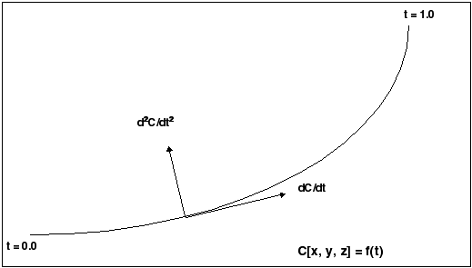
The geometry of each edge or curve is represented as a set of three parametric equations that represent the values of x, y,
and z as functions of an independent parameter, t. The t parameter varies from 0.0 at the start of the curve to 1.0 at the end of it.
The following figure illustrates curve and edge parameterization.

Curve and Edge Types
Solid edges and datum curves can be any of the following types:
| • | LINE—A straight line represented by the class interface pfcLine. |
| • | ARC—A circular curve represented by the class interface pfcArc. |
| • | SPLINE—A nonuniform cubic spline, represented by the class interface pfcSpline. |
| • | B-SPLINE—A nonuniform rational B-spline curve or edge, represented by the class interface pfcBSpline. |
| • | COMPOSITE CURVE—A combination of two or more curves, represented by the class interface pfcCompositeCurve. This is used for datum curves only. |
See the section Geometry Representations for the parameterization of each curve type. To determine what type of curve a pfcEdge or pfcCurve object represents, use the method wfcWEdge::GetEdgeType or pfcCurveDescriptor::GetCurveType.
Because each curve class inherits from pfcGeomCurve, you can use all the evaluation methods in pfcGeomCurve on any edge or curve.
The following curve types are not used in solid geometry and are reserved for future expansion:
| • | CIRCLE (pfcCircle) |
| • | ELLIPSE (pfcEllipse) |
| • | POLYGON (pfcPolygon) |
| • | ARROW (pfcArrow) |
| • | TEXT (pfcText) |
Composite Curves
A composite curve is a curve that is made up of more than one segment and has no geometry of its own. A curve descriptor is
a data object that describes the geometry of a curve or edge.
Methods Introduced:
| |
| |
| |
| |
Use the method wfcWCompositeCurveDescriptor::Create to create an instance of the object wfcWCompositeCurveDescriptor that contains information about the curve geometry of the specified composite curve.
In the curve descriptor, use the method wfcWCompositeCurveDescriptor::SetCompDirections to set the direction of the component for the composite curve. The valid values for the direction are defined by the enumerated
type wfcCurveDirection and are as follows:
| • | wfcCURVE_NO_FLIP |
| • | wfcCURVE_FLIP |
Use the method wfcWCompositeCurveDescriptor::GetCompDirections to get the direction of the component of the specified composite curve.
Use the method wfcWCompositeCurve::GetCompDirections to get the direction of the component in a composite curve.
Evaluation of Curves and Edges
Methods Introduced:
| |
| |
| |
| |
| |
| |
| |
| |
| |
| |
The methods in pfcGeomCurve provide information about any curve or edge.
The method pfcGeomCurve::Eval3DData returns a pfcCurveXYZData object with information on the point represented by the input parameter t. The method pfcGeomCurve::EvalFromLength returns a similar object with information on the point that is a specified distance from the starting point.
The method pfcGeomCurve::EvalParameter returns the t parameter that represents the input pfcPoint3D object.
Both pfcGeomCurve::EvalLength and pfcGeomCurve::EvalLengthBetween return numerical values for the length of the curve or edge.
Use the method wfcWCurve::GetCurveData to retrieve the geometric representation data for the specified curve.
Use the methods wfcWCurve::GetColorType and wfcWCurve::SetColorType to get and set the color of the specified curve using the enumerated type pfcStdColor.
Use the methods wfcWCurve::GetLineStyle and wfcWCurve::SetLineStyle to get and set the linestyle of the specified curve using the enumerated type pfcStdLineStyle.
Solid Edge Geometry
Methods Introduced:
| |
| |
| |
| |
| |
| Note
The methods in the interface pfcEdge provide information only for solid or surface edges.
|
| |
| |
The methods pfcEdge::GetSurface1 and pfcEdge::GetSurface2 return the surfaces bounded by this edge. The methods pfcEdge::GetEdge1 and pfcEdge::GetEdge2 return the next edges in the two contours that contain this edge.
The method pfcEdge::EvalUV evaluates geometry information based on the UV parameters of one of the bounding surfaces.
The method pfcEdge::GetDirection returns a positive 1 if the edge is parameterized in the same direction as the containing contour, and –1 if the edge is
parameterized opposite to the containing contour.
Use the method wfcWEdge::GetEdgeType to return the type of the specified edge.
Use the method wfcWEdge::GetEdgeVertexData to get a list of the edges and surfaces that meet at a specified solid vertex using the enumerated type wfcEdgeEndType. This method returns NULL if the specified edge is not visible in the current geometry.
Curve Descriptors
A curve descriptor is a data object that describes the geometry of a curve or edge. A curve descriptor describes the geometry
of a curve without being a part of a specific model.
Methods Introduced:
| |
| |
| |
| |
The method pfcGeomCurve::GetCurveDescriptor returns a curve’s geometry as a data object.
The method pfcGeomCurve::GetNURBSRepresentation returns a Non-Uniform Rational B-Spline Representation of a curve.
Note
Use the method pfcGeomCurve::GetCurveDescriptor to get the geometric information for an edge, access the pfcCurveDescriptor object for one edge using .
The method wfcWSolid::GetCurve returns the curve handle for the specified curve Id.
The method wfcWCurve::GetCurveData retrieves the geometric representation data for the specified curve.
