Geometry Traversal
This section illustrates the relationships between faces, contours, and edges. Examples E-1 through E-5 show some sample parts and list the information about their surfaces, faces, contours, and edges.
Example 1
Image
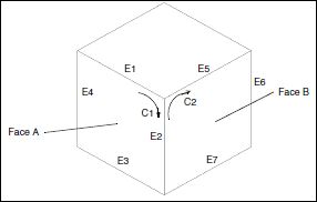
This part has 6 faces.
•  Face A has 1 contour and 4 edges.
•  Edge E2 is the intersection of faces A and B.
•  Edge E2 is a component of contours C1 and C2.
Example 2
Image
Face A has 2 contours and 6 edges.
Example 3
Image
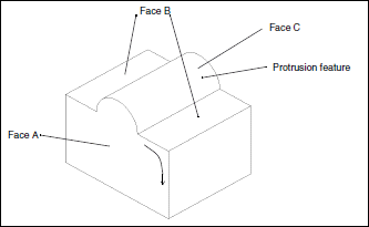
This part was extruded from a rectangular cross section. The feature on the top was added later as an extruded protrusion in the shape of a semicircle.
•  Face A has 1 contour and 6 edges.
•  Face B has 2 contours and 8 edges.
•  Face C has 1 contour and 4 edges.
Example 4
Image
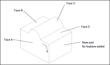
This part was extruded from a cross section identical to Face A. In the Sketcher, the top boundary was sketched with two lines and an arc. The sketch was then extruded to form the base part, as shown.
•  Face A has 1 contour and 6 edges.
•  Face B has 1 contour and 4 edges.
•  Face C has 1 contour and 4 edges.
•  Face D has 1 contour and 4 edges.
Example 5
Image
This part was extruded from a rectangular cross section. The slot and hole features were added later.
•  Face A has 1 contour and 8 edges.
•  Face B has 3 contours and 10 edges.